Trailers - Design & Build
C. TRAILER TONGUE
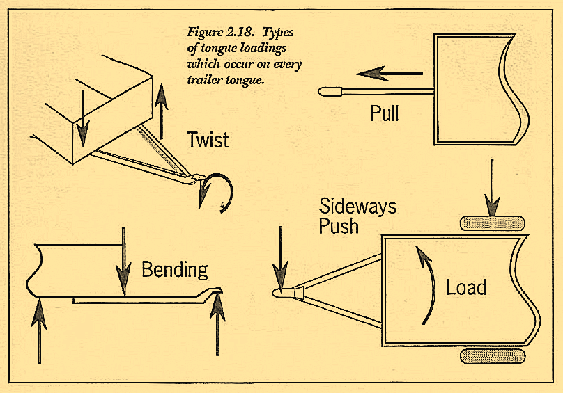
Within the framework, certain areas require and deserve more attention than others. The design of the tongue is one of those areas. The tongue is not simply a way to attach the trailer frame to the tow-car; or, as is commonly thought, something used for pulling the main body of the trailer forward. Ah yes, it is indeed that, but it is much more. Other substantially higher loads exist that must be considered. Bending from downward weight, twist from bumps and side to side differential loading are a few worth mentioning. Ignoring these other loads, some of which are illustrated in Figure 2.18, can cause you to create a tongue incapable of supporting them. Be aware that an increase in tongue weight (often from load repositioning) or a rearward movement of the axle can substantially increase stresses on the tongue. Inadequate tongue design invites deformation and cracking as well as the potential for breaking. No question about it, this portion of your design deserves your undivided attention.
Attachment methods (tongue to the trailer body) are as varied as trailers themselves-on top of the frame, under the frame, butt welded to the front of the frame, or a continuation of the main frame rails (as in a boat trailer). The boat trailer’s method of a continuous structure avoids a connection altogether since it is already one long piece. Assuming the material is large enough to handle the maximum loading and adequate lateral bracing is provided, it is, from my observation, an excellent solution. Using the same material the full length of the trailer adds a certain amount of additional weight in areas where less load is carried. However, welded joints and connections which may be more susceptible to fatigue and cracking are not lurking about. Unfortunately, in most trailer designs a continuous framework is not appropriate and a connection must be devised.
Tongue attachment points-to frame, to coupler-are considered “joints” in engineering terminology. Joints of any kind rank as the most difficult of design challenges. In addition to the ever present risk of separation, the potential for stress concentrations from holes, welds and changes in cross section, is much higher than with continuous material. Joints include connections made with welds, bolts or rivets and are covered in depth in Volume 2. In whatever way one configures a joint, the area should be carefully studied for not only the type of loads to be carried but the magnitude and direction of these loads along with the potential fatigue characteristics. Once the loading in the area is understood, a suitable design and resistance to it is much easier to produce.
Tongues that are butt welded to the front cross-brace of the framework are quite common and often downright scary. In checking out trailers at the races, I frequently find cracked welds in this area. Recently, though, an even more alarming home-built trailer crossed my path at a traffic light. As it bounded through the intersection a 3 to 4-inch bending of the frame at the tongue-to-frame attachment was visible. I stared in amazement and decided to follow. When I pulled up next to this newly licensed trailer, I could see why its body gyrated like a hula dancer. Figure 2.19 is a side view drawing (I was caught without my camera) of the tongue connection as I saw it. Even though the tongue was triangular, from a top view, it attached to the frame at only a single point in the side view (a line in any other view).
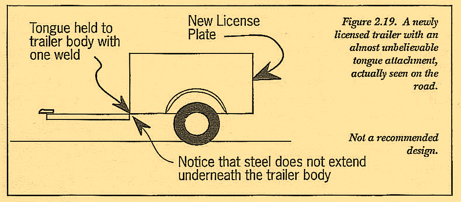
actually seen on the road.
It was only a matter of time before fatigue of the tiny amount of weld area produced a most unpleasant surprise. I flagged the non-English speaking gardeners over to the side of the road and demonstrated their problem by pushing down ever so little on the front cross panel. The tongue-to-frame connection point dipped about 3-inches. Hopefully I communicated the solution and the trailer got fixed. Unfortunately this occurance is not all that uncommon since there are no standards or guidelines for anyone to follow; and licensing procedures have nothing to do with trailer design or adequacy.
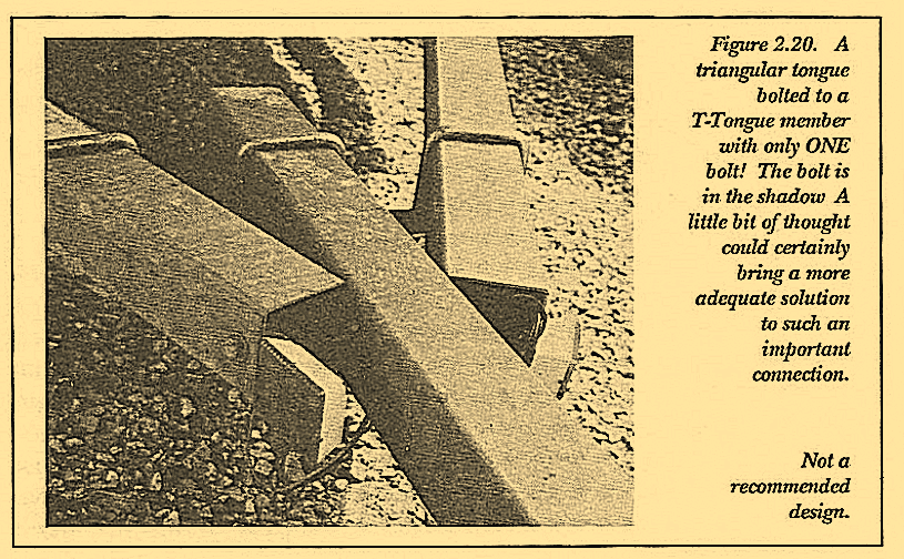
Figure 2.20 is, in my view, another marginal tongue connection. The triangular legs are held to the straight leg with only ONE bolt-this is all that holds the coupler to the body of the trailer with its cargo. The U-bolts are used to resist bending and would do little to hold the center tube if that one center bolt broke. In addition the wiring access hole is placed in a highly stressed area just in front of the single bolt connection. Notice also there is no rubber grommet in the hole to insulate the wires from the sharp metal edges; not even a second jacket around the two wires for protection. A torched hole with its melted edges would be better protection for the wire. And a wire hole behind the bolt would create less weakening in an area most important for structural adequacy.
The tongue in Figure 2.21 is a T-tongue with a design which has totally ignored the loadings just described. Two spindly attachment points lacking any form of lateral support are all that hold this tongue to its body. The welds completely encircle the tubing eliminating any continuous material from front to rear.
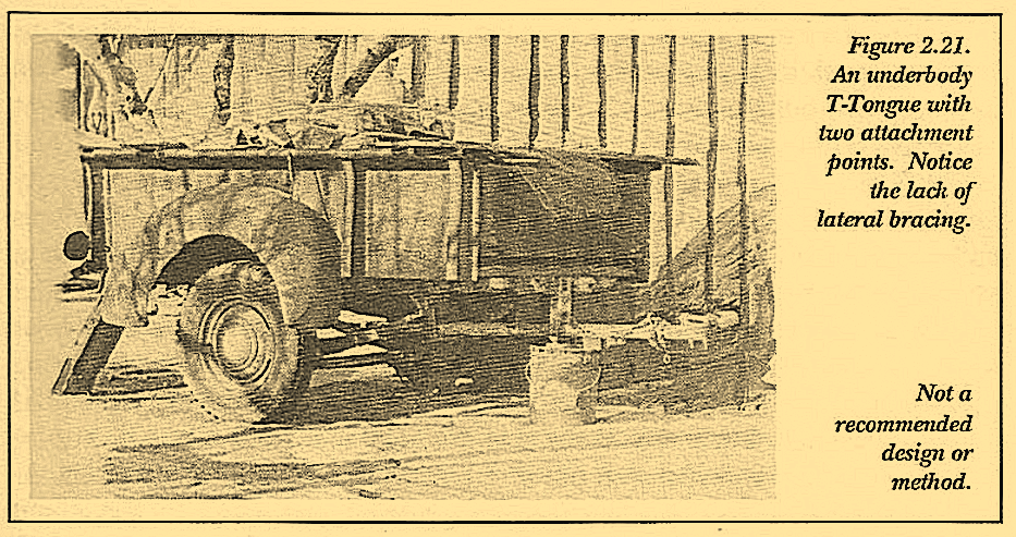
This weld embrittled circle make this area a high risk candidate for fatigue failure. In addition, the two drop down arms will need constant scrutinizing to detect the need for ever recurring repair.
Another tongue configuration to avoid is the one in Figure 2.22. Although triangular, it is so short one’s tow vehicle could barely, if at all, make even the smallest of turns without a crushing event at the corners. The back of the coupler is only an inch or two in front of the spare tire’s forward edge. This tongue’s short length of about 2-ft is a serious potential problem for towability. Almost any speed above 35-mph could easily toss this little gem into uncontrollable sway. Let’s just hope the tow vehicle is LARGE.
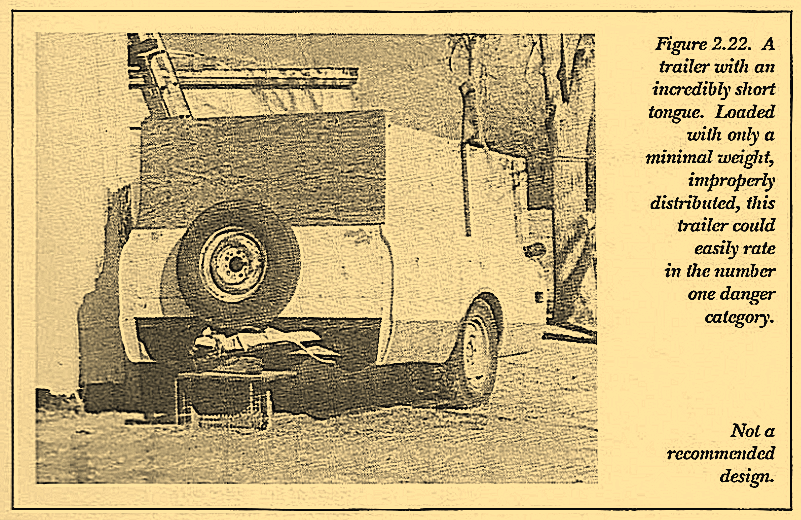
trailer could easily rate in the number one danger category. Overall Considerations Not a recommended design.
I have found truck bed trailers to require special considerations including sufficiently long triangular tongues. And to help balance the extra long rear overhang and forced higher CG, the longer the tongue, the better. The effect of these configurations is discussed in more detail in Volume 2.
Trailer tongues although very different from each other, generally conform to two standard formats-T-tongue style or triangular, sometimes called an A-frame tongue. The T-tongue can be a straight piece of tubing, pipe, or channel protruding from under the frame. This style of tongue usually attaches to a perpendicular cross piece. Twist, bending and shear loads must be carried with only one beam instead of two. To be as strong as a triangular tongue, a T-tongue must be a much stouter piece of material and be attached extremely well. In most instances it will also require diagonal reinforcing which sort of turns it into a triangular shape anyway.
In spite of the inferiority, T-tongues turn up on many trailers-light ones to mid-weights . . . and even on some heavy weights, as we have seen. Most trailer designs appear to have been built with the mistaken notion (already discussed) that the load is only pulled-not twisted, not bent, not vibrated. A T-tongue beam can resist these loads if it is big enough and the frame attachment is designed carefully. If the trailer is then never used beyond the tongue’s capability, few problems are apt to appear. Unfortunately the risk of overloading a T-tongue is great.
On the other hand, a properly designed triangular tongue, for only a little more work and expense, will carry more of the prevalent loads in a more efficient manner than the T-tongue. Your trailer will be happier and so will you. Benefits of the triangular style tongue are numerous. The “load path” is smooth and far superior to that of the T-tongue. The loads at the coupler are pulling in an almost straight line from the spring-to-frame pick up points. (See Trailers-How to Buy and Evaluate.)
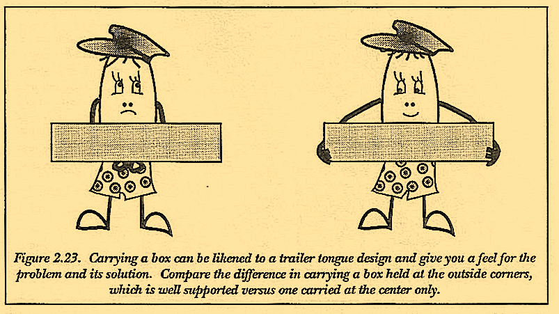
In contrast, the “sharp 90° turns” of the T-tongue design serve only to aggravate an already inherently weaker structure. Tongue leg material at the extreme outer points support just about any twisting of the trailer body. The one spindly leg of the T-tongue has little to resist this twist; thus loads on the welds (and structure) are very high. To illustrate this point, imagine carrying a box of steel parts about 30″ long, as in Figure 2.23. Moving this box is considerably easier by lifting it with two hands, one at each end, rather than trying to balance it with one arm right in the center. Try it!
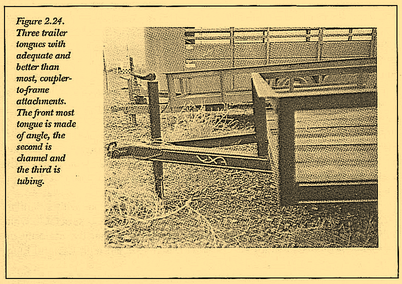
The trailers in Figure 2.24 and 2.25 are, in my view, closer to having tongues of secure and appropriate design. They are all triangular and all have couplers welded solidly onto their fronts. Couplers welded with both longitudinal, vertical and horizontal welds, as is possible with this design, are quite superior to couplers placed on top of the tongue legs using only longitudinal welds to secure them. The tongue closest to the viewer in Figure 2.24 is made of an angle cross section. This choice reduces the trailer’s overall strength and is not consistent with the weight and mass and loading capability of the trailer body. The tongue’s inadequacy may result in early wear and fatigue. Close examination of the tongue-to-frame point already reveals a small amount of distortion. This a relatively new trailer with fresh paint and comparatively little wear and tear. An additional piece of angle welded to the bottom of the existing angle to form a channel or boxed section would improve the strength of this tongue immensely.
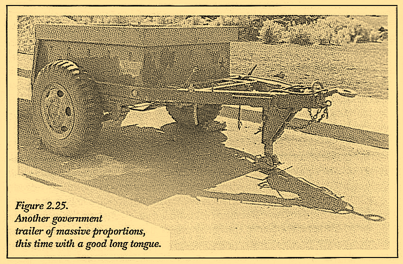
The tongue of Figure 2.25 is well built and massive and fits the pattern of many found on government trailers. This tongue is made of two pieces of channel per side overlapped top and bottom and welded together into a tube shape. A tube of this cross section is strong in areas where the most strength is needed. The loads at the front spring perch are directed straight to the coupler via the triangular tongue legs. This is as it should be. The massiveness of this trailer is not particularly appropriate for consumer or even commercial use due to its deleterious effect on handling. Nor is the CG height conducive to high speed towing. But government trailers seldom exceed 45 mph and the ratio of tongue length to rear overhang helps to balance this trailer’s other drawbacks.
The trailer of Figure 2.26 is another massive number. This shorty probably weighs more than it will safely carry. It is obviously a pick up bed complete with original axle, suspension, wheels and tires. The entire truck frame (the primary culprit of its overweightness) was left intact and cut far enough forward under the cab that bending it easily created the tongue-clever, huh? The coupler is solidly attached with all around welds and with a tongue a foot or two longer, it wouldn’t be too bad of a design. except for its mass to cargo ratio.
The trailer of Figure 2.27 is another truck bed trailer with a similar massive tongue and frame. The variety of trailer frames constructable with a truck bed body bogles the mind. It is unfortunate that the majority of tongues are built so short that no compensation for the high CG and long rear overhang is incorporated.
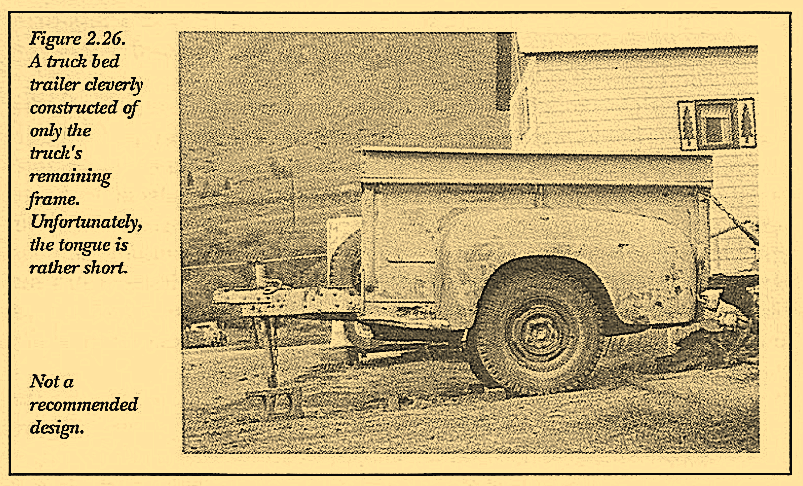
rather short. Not a recommended design.
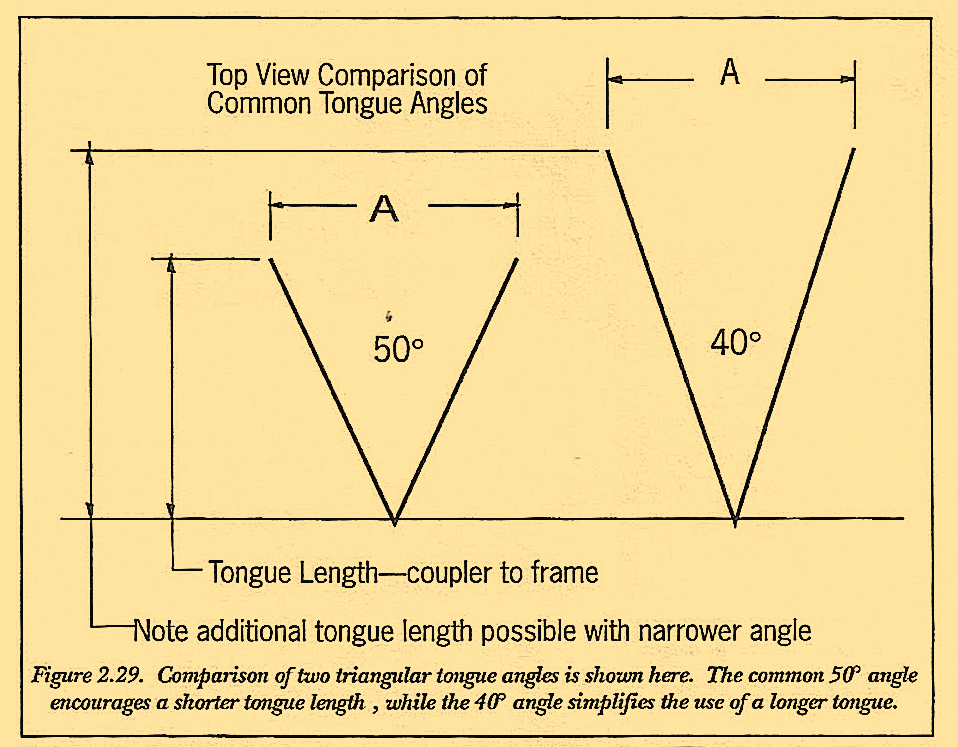
Triangular tongues, although superior to T-tongues, are not all the same, as you have no doubt just noted from the given examples. The nose angle of the triangular tongue can make a world of difference. Commonly the angle is 50°. This angle is popular because of precedence set by coupler manufacturers who make couplers with this angle. Asking questions around the industry, reveals that no one seems to have thought about any other angle. Why? I don’t know. After studying the causes for trailer sway, I find the 50° angle unfortunate. It seems to encourage shorter trailer tongues and the use of straight axles, both of which have a less than desirable effect on stability. Economics and an industry steeped in tradition have made it difficult to influence changes.
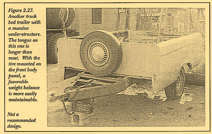
tire mounted on the front body panel, a favorable weight balance is more easily maintainable. Not a recommended design.
Fifty degree couplers create a tongue that can be welded under the trailer bed, producing the most convenient coupler height for hitch attachment when a straight axle is used. Straight axles are popular because of reduced labor to manufacture and resultant lower cost. After all there are no bends or complicated welds, only machining of the spindles. This combination is the least expensive approach to trailer building, thus its popularity. The resulting tongue length of 3-feet (plus a little) is just the right length to miss the tow vehicle rear fender in a tight turn. In addition, a shorter tongue length facilitates storage in small places, hence the justification for this angle and the shorter tongue.
It seems to me the criteria for tongue length should emphasize performance at towing speeds rather than parking convenience. Figure 2.29 compares the difference in length of tongue for two different angles using the same rear width as the control dimension. Notice that the 40° angle permits a much longer tongue.
Low bed heights are also desirable for improvement in handling and the attendant ease of loading. With a drop axle and an under-the-frame tongue, the need to step the coupler up to a standard height of 17-in to 21- in becomes apparent. Methods employed to achieve this are numerous as can be learned by studying Figures 2.31 to 2.34. These entertaining examples are attempts to fill this need. Perpetrated no doubt by the lack of products to serve their function, these homebuilt solutions are also structurally alarming.
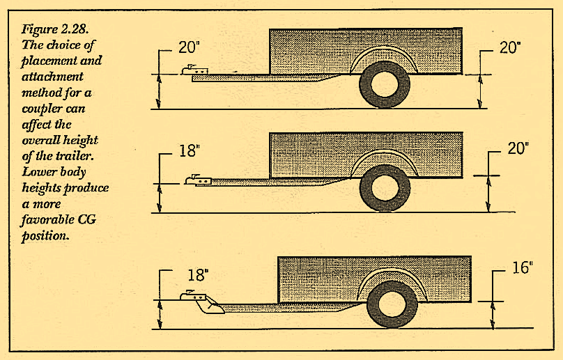
heights produce a more favorable CG position.

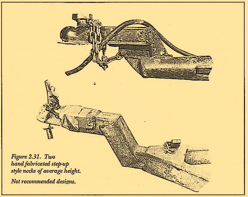
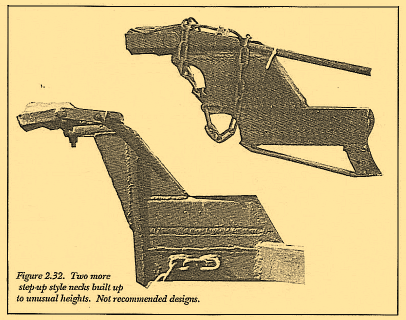
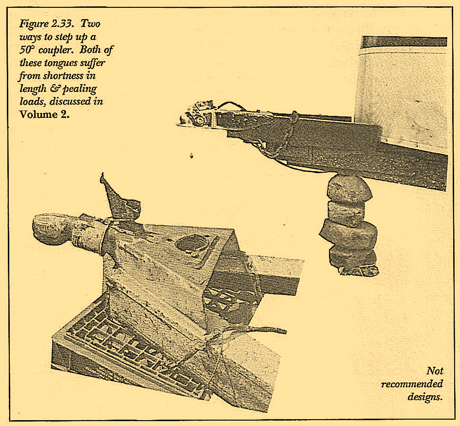
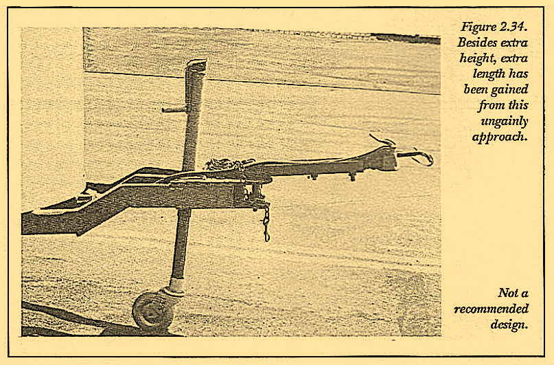
Each of these creations have required a large amount of work to achieve the stepped up height and lower bed. Even the 50° coupler of Figure 2.33, normally set up for wrap around welds, falls short of sound design practice since its fabricated block sits atop the two tongue legs permitting only the longitudinal welds for connection.
While few companies will take the time or risk of developing such a product, this author has thought about this problem extensively and produced a solution that not only provides a smaller angle encouraging the sought after longer tongue, but permits the dropping of tongue legs to create a lower center of gravity.
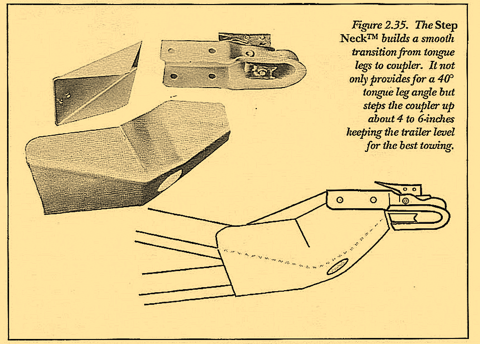
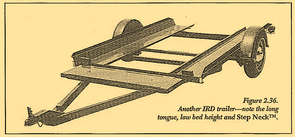
This product, dubbed the Step NeckTM is patented and shown in Figure 2.35. Compare its 40° angle to the common 50° angle tongue. The Step NeckTM mounting also encourages use of a drop axle. Thus even though the bed is low, tongue legs are even lower and can extend under the main frame permitting a larger area for welding and fastening. Loads then carried by the weld (or fasteners) are also spread over a larger area and the load per inch of weld or fastener is then reduced, creating a stronger connection. The trailer in Figure 2.36 is an IRD creation using the Step Neck TM. Note the long tongue and depth of drop down between the axles. If you are interested in further information about this product, contact the publisher for current status and availability.
