Trailers - Design & Build
Brakes-Hydraulic
Hydraulic brakes do not use any form of electricity and are much like the ones on your automobile. Hydraulic fluid is compressed through a tubular line which actuates a cylinder on the backing plate that then expands the brake shoes. The initiation of fluid flow through the brake lines to the brakes can be accomplished by either an actuator or a special attachment to the tow vehicle hydraulic brake lines.

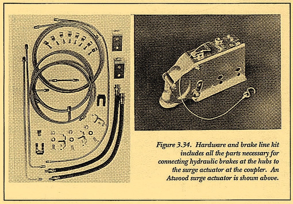
The first method requires installation of a special coupler called a surge actuator. Figure 3.32 shows several of these devices while Figure 3.33 and 3.34 show the hardware and brake line kit required to connect the two.
The actuator/coupler is welded to the nose of the trailer in place of the standard coupler. This specialized part contains a ball cup like most couplers which is part of a sliding mechanism. With one end attached to the tow vehicle, the other end of this sliding member is attached to the plunger of the master cylinder for the hydraulic trailer brakes. When the tow vehicle slows, stops or travels downhill, the trailer pushes forward, as the sliding mechanism is then pushed rearward. The resulting compression of the master cylinder pushes fluid through the hydraulic lines to the brakes at the wheels. The brake backing plates, mounted to the axles, have their own small cylinders which are moved by the compressed fluid. These cylinders open the brake shoes thereby applying the brakes. The ability to confine this system to the trailer alone encourages its use on trailers where different tow vehicles are to be used. Hence most rental yards choose this style over electric brakes. Boat trailers that are continually backed into the water prefer hydraulic brakes which are less susceptible to rust than electric brakes. Rust is not conducive to electrical conduction and can render the electric brakes inoperative.
The surge/hydraulic system is, however, not without disadvantages. Some of the problems encountered are 1) on steep downgrades, the brakes can be on all the time causing them to overheat and fade; and 2) a normal brake application with a heavy trailer may result in violent “bucking” or “surging”; 3) in the event of a sudden advanced trailer instability, surge brakes provide little help in restoring calm.


However, in first heading downhill, these brakes may be helpful in keeping the rig below the critical speed where sway can begin. TRAILERS-How to Tow and Maintain describes these potential problems in more detail, and troubleshoots remedies.
In the past special connectors have been rigged to the tow vehicle’s hydraulic brake lines. This eliminates the surge actuator and more effectively integrates the trailer braking system with that of the tow vehicle.

Shown here are the following surge actuators:
1 – Atwood, Unique Functional Products and Dico.
The bottom photo is NOT the proper installation method for at least 3 reasons:
1)the coupler is welded to the actuator slide tube with minimal welding,
2) both the actuator and the coupler are welded only in horizontal directions, and
3) the actuator is completely inactivated because the inner sliding tube is welded to the outer tube..
However, there is some amount of risk that improper installation could cause disruption or failing of the tow vehicle’s braking system. Because of this along with greater expense and disapproval from auto manufacturers this method has never received wide acceptance.
Attachment of these surge actuator/couplers to the trailer is an area where attention is important. Several examples are shown in Figure 3.35. The first coupler shown here is manufactured by Atwood and is admirable in several ways. The loads have apparently been carefully evaluated during the design process. This coupler easily fits over 3-inch material, a very common size at the trailer nose. Angled tongue legs can also be specially mitered and welded to the sides of the coupler body at any angle according to the included instructions. In addition, the forward motion of the trailer rocks the coupling portion around a heavy duty pin joint which is positioned for easy detection of wear or damage. The mounting feature on the second coupler is also well designed, as is its smooth nose area. The third actuator is fabricated from two large pieces of tubing which slide one inside the other. There is no simple provision for slipping the coupler over the top of a frame member on the nose of the trailer. This coupler has to be laid on top of the trailer tongue and welded in place. Without reinforce- ment, the two short welds holding the coupler are then subjected to pealing loads, which are discussed in Volume 2. Pealing loads cause a higher stress level at the pealing corner, making it difficult to calculate the actual load and prepare the area properly. Hopefully the result is not as shown in the fourth illustration where the entire surge actuator is fully disabled with an over zealous welder. With the high rating of these couplers, provision for heavy duty mounting methods are a decided advantage and when not part of the design must be otherwise compensated.

