Trailers - Design & Build
B. TRAILER STRUCTURE
The trailer’s framework and structure is its backbone and the skeleton to which all parts are attached. It determines ultimate strength and useability. Its configuration can vary extensively and will be greatly affected by the materials used. The framework will determine the trailer’s ability to carry your cargo. Indeed, you must admit, an attempt to carry a boat on a horse trailer would be pretty ridiculous, and vice-versa even worse. Besides pure useability, design will have a great effect on the trailer’s stability, in addition to its suitability for use with your tow vehicle. No wonder the framework design is so important. If done properly, framework design is one of the most difficult steps to complete.
As many seem to think, a trailer is NOT just an axle, wheels, tires and a coupler. It is a complex conglomeration of many different material shapes and sizes, a myriad of odd and unusual parts including the more obvious just mentioned ones. Suspensions alone can contain over 25 different types of parts, and well over 100 parts all summed up for the whole trailer. Frameworks suffer no simpler agglomerations with main rails, cross members, tongue pieces, braces, brackets, lights, accessories and so forth. Much study, work and thought are required to co-ordinate the construction of such a complex assemblage of parts; that is, if you want to do it right. Manufacturers in the business face almost insurmountable inventory problems especially if customized designs are offered. The trailer design task along with the need for planning certainly should not be underestimated.
What parts of the trailer are considered to be the framework? The tongue, the longitudinal members, the cross-braces and sometimes the bed, although the bed may often just sit on top. In a covered trailer, the members supporting the walls and roof are also considered framework. Deciding what materials to use for each of these parts can be quite a chore. The material has to be strong enough, but too strong quickly makes a trailer too heavy; thus it has to be light enough. The shape has to be right and correctly positioned for the load bearing on it. Questions one might ask are: Is it low enough, wide enough, high enough? Does it need sides? What kind of cross-bracing? Where to place the cross-bracing? How should the tongue be constructed? Where to store the loading ramps or the tailgate, if any? Fitting these and a mile long list of other requirements into one trailer is the challenge of designing and creating the ultimate.
Cargo position, material, capacity and end use must be considered simultaneously when laying the groundwork. This sounds like a tall order and can be overwhelming. The trick is to look at one part at a time then the next, then the next. When each individual area seems to make sense, compare and combine them.
Some people refuse to do this preliminary work because it is just too involved. Others don’t even realize that it should be done. Results for these people are often very different than expected. After years of waiting to have time to do it, a friend of mine built a trailer he considered to be the ultimate. He designed it for a gross of 5000-lbs because he wanted to carry about 3500-lbs. He used the best and strongest tubing he could find. He laid it out on his garage floor and assembled it as he went. He wanted to be sure the trailer was plenty strong and would take a beating. When the Motor Vehicle Department required a certified weight on the trailer, he was aghast to find the trailer all by itself weighed 4000-lbs. Don’t laugh! This is not a difficult thing to do. It happens all the time to almost every project where planning, drawings and calculations are not part of the process. With a drawing and weight calcs in advance, this could have been predicted and even prevented. With a drawing, weight can be saved or added as required.
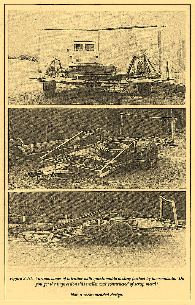
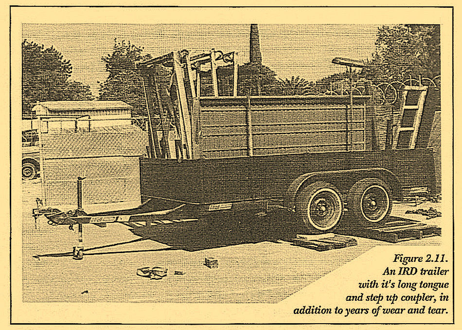
Poorly planned and under performing trailers are easy to find. Figure 2.10 is such an example. This trailer obviously grew from spare pieces of steel and an initial angle framework . . . as many do. My guess is that when the small angle and large flat surface were tested with the desired load, it didn’t work too well. So the front cross-brace and side truss were added along with the doubled tongue. The tongue is built up in the vertical direction but lacks horizontal reinforcement. Although the trusses along the side work well to reduce front and rear drooping, the lack of suspension will accelerate fatigue, especially in a trailer with such fragile connections. Hopefully the bar at the rear is not used to tie anything of significance; its anchoring is far from adequate for even a small load applied at the top. (Notice that the left side is already angled forward.) Figure 2.11 is a lightweight car trailer used for the same purpose. It is strong in the areas where strength is required. Even years of wear and tear have failed to create the eyesore of Figure 2.10.
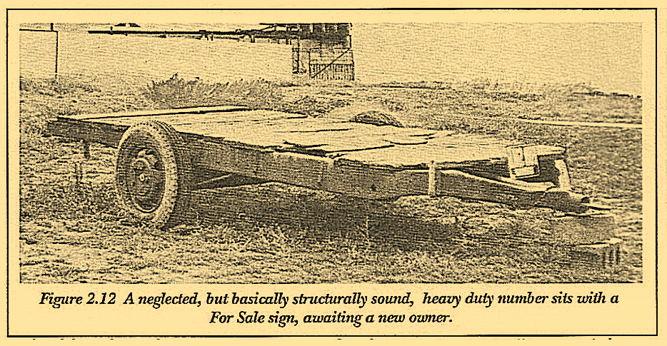
Talk about massive frames. The one in Figure 2.12 is indeed that.
Except for the weathered wood, the frame rails actually appear to be quite light for what they’ll carry and the machine bent tongue is actually stronger than most. The wheels and tires appear to be massive enough to handle the load it was designed for. On the other hand, a trailer of this size should have a tubing tongue or the channel should be made into tubing. For towability, I would like to see a longer tongue, especially in light of the higher CG. And a coupler certainly needs to be added. To think of towing even the weight of the trailer with a single pin of 3/4″ to 1″ diameter is beyond my comprehension. All in all, for a heavy duty trailer, this one looks grubby but structurally is much better than most. If I were in the market for such a trailer, I would purchase it and make the few minor changes to upgrade it with a lunette eye, coupler, fenders and lights as well as repair or replace the wooden bed. It is difficult to tell if suspension exists. If not, this is a definite drawback and may well temper my decision.
Other massive frameworks can generally be found on trailers constructed for the government as shown in Figure 2.13. The size of the bed (5-ft x 8-ft) is small relative to the beefy structure. The heaviest cargo is probably dirt or mud, although the gravel currently in the trailer is no light weight. The most severe survival test, however, is the ability to be dropped unscathed from a helicopter. The suspension, wheels and tires are probably far larger than required for most of its functions, but with a free-fall of any distance, something pretty massive is needed. These trailers are very costly to build and result in a great expense for the government. I’m certainly not recommending all trailers be built in this manner, however, something can be learned from this one.
While we’re talking about large trailers, check out the one in Figure 2.14 and compare it with 2.13. In spite of the diagonal tension bars along the sides, the frame still sags at either end. It is hard to believe that cardboard could be so heavy to create the wear and tear this trailer seems to be experiencing-but indeed it can. Cardboard is definitely not light.

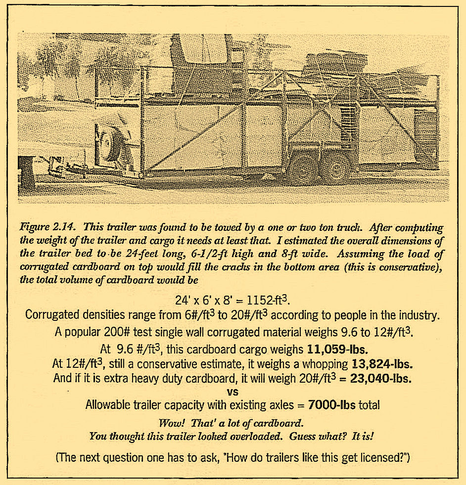
- 24′ x 6′ x 8′ = 1152-ft3;
- Corrugated densities range from 6#/ft3 to 20#/ft3 according to people in the industry;
- A popular 200# test single wall corrugated material weighs 9.6 to 12#/ft3;
- At 9.6 #/ft3, this cardboard cargo weighs 11,059-lbs;
- At 12#/ft3, still a conservative estimate, it weighs a whopping 13,824-lbs;
- And if it is extra heavy duty cardboard, it will weigh 20#/ft3 = 23,040-lbs.
- VS
- Allowable trailer capacity with existing axles = 7000-lbs total
- Wow! That’ a lot of cardboard.
- You thought this trailer looked overloaded. Guess what? It is!
- (The next question one has to ask, “How do trailers like this get licensed?”)
After weighing a small stack of folded cardboard boxes and computing the density to be about 9-lb/ft3, I then checked with a local manufacturer and verified my measurements. By measuring the wheels and scaling the rest of the photo, I calculated the weight of cardboard to be in excess of 10,000- lbs as discussed in Figure 2.14. I bet the owners think their load is much less and they never sat down to really figure it out. In addition, a 24-foot trailer made of channel would have to weigh at least 2500-lbs and maybe even 3500-lbs. The wheels and tires certainly aren’t a style to have a capacity of more than 1800-lbs each, nor will they fit axles of more than 3500-lb capacity. Thus the gross capacity on this trailer computes out to be 7000-lbs in round figures. Yet the cargo and trailer together weigh more than 11,000-lbs (a 50% overload) or 14,000-lbs (a 100% overload).
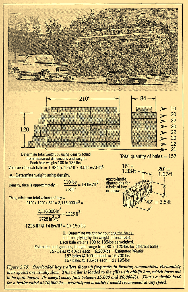
This story is not so uncommon. The hay trailer in Figure 2.15 is another example of overloading, although the percent overload is not as great. The weight of the hay calculates out to weigh about 14,000-lbs. This wouldn’t be so bad if the trailer had three axles and the tow truck was at least a one ton model. But the axles are a 5200-lb mobile home style and there are only two of them. The truck appears to be a 3/4-ton model. Hopefully the chosen journey is short and slow and on smooth roads. On another outing, I followed a similar truck and a load and believe it or not, a similar amount of hay was carried on an even less adequate trailer more like the one in Figure 2.14.
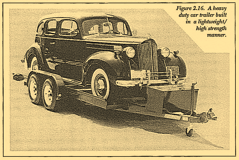
The car trailer of Figure 2.16 is rated to carry 5000-lbs. Its total weight is about 1500-lbs, even with the tool box. For a 7000-lb gross, a payload of 5500-lbs can be handled. But the wheels and tires don’t come large enough, so the top capacity is actually 6800-lbs less 1500-lbs, for a net load of 5300-lbs. These kinds of calculations need to be run through for each combination of loading and trailer pair. The trick to keeping weight under control is to use material as light as possible (using calculations as a guide) and reinforce in highly stressed areas, but reinforce smoothly. Notice the tongue stiffeners where the tongue attaches to the front cross member. Similar reinforcements are used extensively under the trailer.
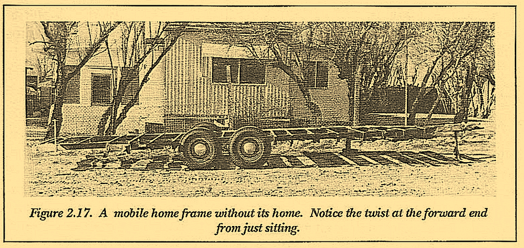
To understand this a little more, study the mobile home frame of Figure 2.17. Before a house is added, these frames are very floppy for their weight. A slight twist is even visible in the picture if studied carefully. A larger twist is possible by stepping on one corner. These are not good frames to make into flatbeds because they are heavy and inefficient.
They are designed to depend largely on the addition of a house frame to provide stiffness and strength, particularly for twisting. The trailer of Figure 2.17 has no house to stiffen it. Thus the longer a frame like this becomes, the more twist and floppiness can be expected. Mobile home trailers are notorious for being designed to just do the job intended. It is fortunate they spend little time on the road and this is the excuse for their marginal nature. Used beyond the task of toting a home from mobile home park to mobile home park they often reach their limits quickly.
Careful analysis of weight requirements and materials before you begin construction will avoid these mistakes and give that needed opportunity to develop the best design. Strength with lightness must be the goal. For a given gross weight, the lighter the trailer, the more remains available for cargo. Although this seems obvious when mentioned, many people prefer to ignore it and their trailers become very heavy. Large semi- trucks are constructed mostly of aluminum-siding, framework, wheels-to save weight. A few parts, such as axles and main rails, are steel primarily because of cost and other trade-offs which make steel more desirable.
Steel shapes can, in fact, be formed to produce a lot of strength with lightness at a lower cost than aluminum and can often then compete with aluminum for lightness. Volume 2 discusses this subject in more detail and the charts in its Appendix list properties for many shapes of material. Some of the formed steel shapes were developed, proven and used for many years by IRD Trailers.
By modifying the shape of the material rather than selecting formed hot rolled shapes, lighter sections are achievable. The more work one piece can do, the lighter your trailer will be. For instance, a car trailer often uses runners to guide the wheels. The runners can be placed on top of a frame resulting in additive runner and frame weights. Or the runner can be designed as a major structural member eliminating additional frame pieces.
Two purposes are served and considerable weight is saved. Material selection charts can be studied to develop a sense of important relationships and the manner in which the numbers change as the shape changes.
