Trailers - Design & Build
A. THE ESSENCE OF CG.
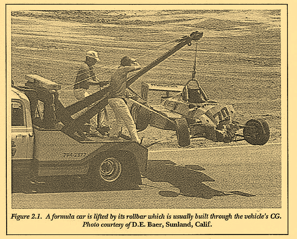
The point from which an item can be lifted with perfect balance is called its center of gravity. For example, a formula type race car can often be lifted by its roll bar and remain level as it is carried off the race track by a tow truck (See Figure 2.1). It is being lifted through its horizontal CG. Machinery is often fitted with a loop for lifting with a chain and forklift. As the machine is lifted it will not tilt from side to side. It also is being lifted through its horizontal or lateral center of gravity. Trailers have a CG, too, just like every other physical body. Knowing the position of that CG can help you determine a trailer’s suitability for being towed.
Finding the horizontal CG of many items is usually easy. Figure 2.2 demonstrates the weighing of an object to obtain its actual CG. (NOTE: This lifting and weighing must be approached with great caution and safety and should only be attempted by persons with experience in this area.) Weigh each end of the item and calculate the center point as in Figure 2.2. Determining the vertical CG position requires a little more tenacity. The simplest way is to turn the item on its side and find its balance point in the same manner we did the horizontal CG.
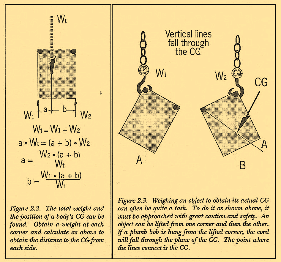
Unfortunately, this method is often not too practical. Another way is to lift the item from an upper corner (if angling it is acceptable) with a spring scale attached. This will permit the reading of a weight and provide a vertical line from the lifted corner through the center of weight. This line can be marked on the side of the machine. Do the same with another corner. The intersection of the two lines is the CG-both horizontal and vertical placement. This method is not without risks, though. Damage to you or the equipment-if it should slip-is a real possibility. Please take special precautions and have someone around that knows something about the safety procedures necessary for such a task. Accurate measurements are important and if not obtained, the reliability of the resulting numbers will suffer.
The CG can also be calculated. as long as one knows the weight of each piece and the exact locations of the CG of each individual part. This method can be fraught with inaccuracies because of all the little pieces that are too easily missed, such as welds or oil in containers.

Knowing or finding the CG of each piece is a tedious task. Each piece has to be measured, calculated and the CG found separately. Figure 2.4 illustrates this method. As you can see, one is left with choosing among a few less than desirable methods and realizing the potential for inaccuracies.
If you are attempting to determine the CG of a trailer that hasn’t been built an even greater challenge awaits you. However, if you don’t find a way to at least estimate it, the consequences could be dire indeed as can be observed by studying Figures 2.5 through 2.7. Figure 2.5 is a trailer I followed for several city miles. Its body roll caught my eye as it left a supply house dock. Many factors are alarming about this example. The overload is evident from the curve of the axle and camber of the wheels and tires.
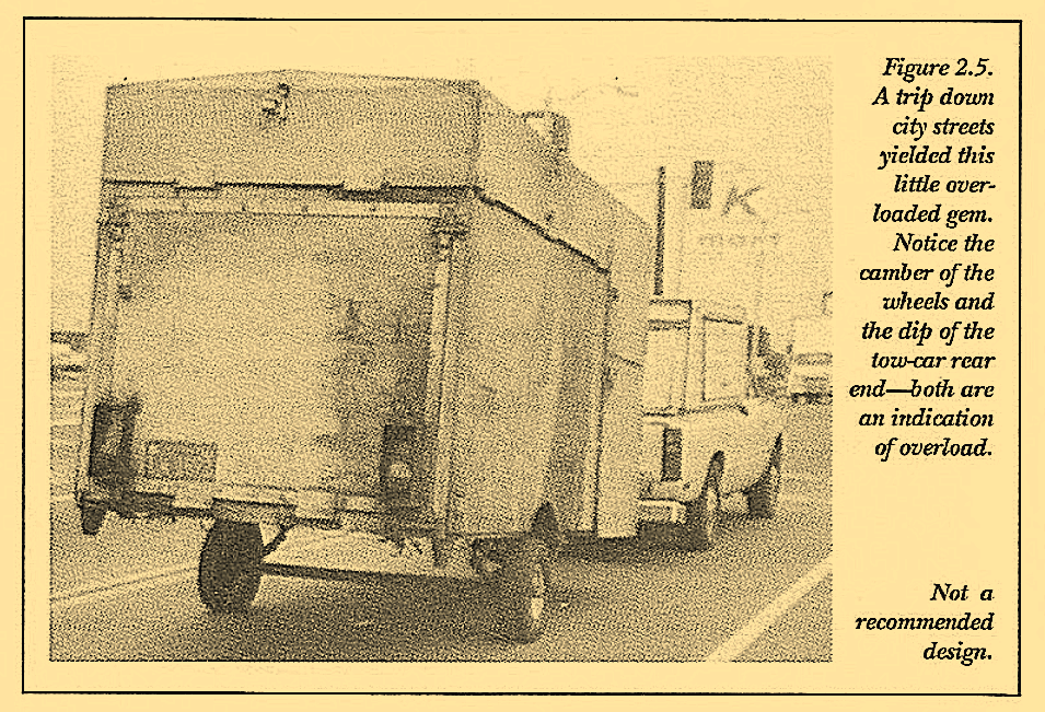
In addition, the lowered tail of the tow vehicle suggests an excessive tongue weight. Although this could occur from a load bias toward the front of the trailer, the other factors suggest it to be an overall load excess. In motion, the body roll was severe and aggravated by the body being built over the top of the small tires and the meager T-tongue. I was grateful to observe the trailer did not exceed 35-mph while I was watching.
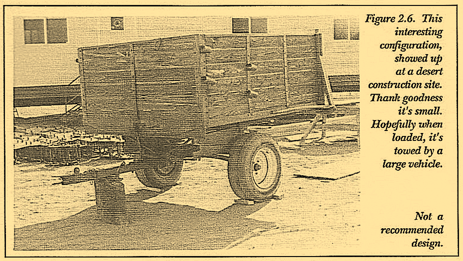
Talk about high CG’s, the trailer in Figure 2.6 has to take the cake. Used around a farm at 5-mph, this trailer would be its dutiful best. Unfortunately, if loaded full on public roads, this little gem could be lethal indeed. We put numbers to this trailer’s dimensions in Volume 3, where you will see what we mean.
The trailer in Figure 2.7 is another contender for top prize. At least the body fits down between the wheels and the tires are a decent size. The trailer’s downfall is first, its loosely constructed wooden body, in addition to its resulting CG position up and over the automotive differential axle in addition to the long soft springs. The spindly unreinforced T-tongue would provide little resistance to instability or sideways swings which are certainly invited by the the short tongue and long springs. Other points of interest are the decorative fenders, one bald tire and the heavy wooden box held with steel banding material (which I found in my own experience breaks very easily with stretching impact loads). I would recommend low speeds, light loads and close-to-home activities for this little number. You see how easy it is to end up with something less than desirable?
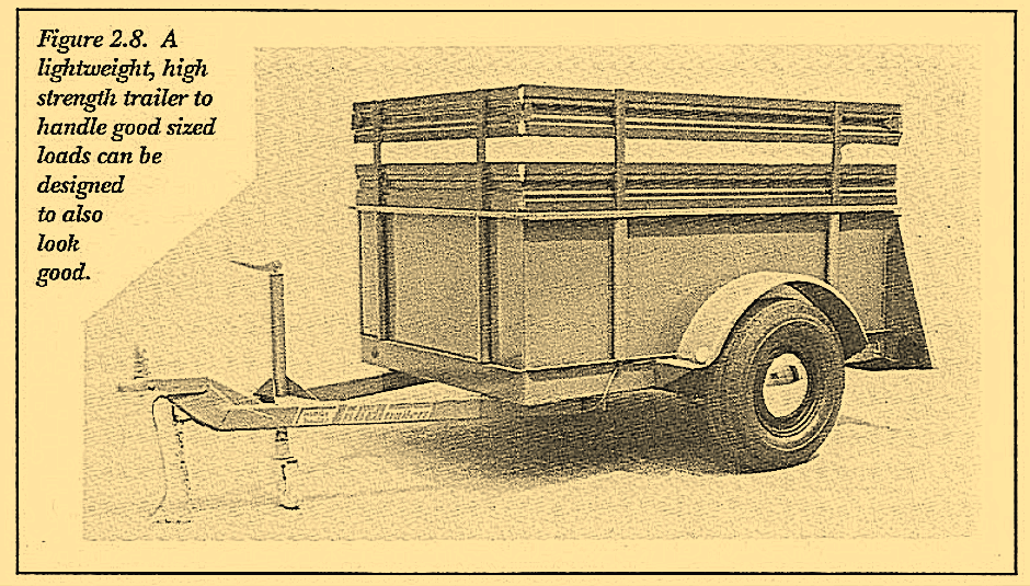
If these trailers had been drawn up and laid out on paper first, problems could well have been recognized in advance and results may have been as the trailer shown in Figure 2.8. If dimensions or components need to be modified to position the CG correctly, it is much easier to do so before things are welded in place.
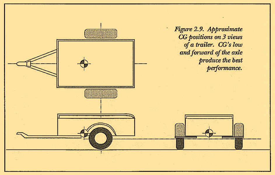
The trailer shown in Figure 2.8 has not only a bed that sits down between the wheels but also short stiff springs, a long tongue and a CG that is low and forward. Ideally towing trailers are designed in a similar manner with the horizontal CG position in front of the axle, the vertical CG only slightly above the wheel centerline and the lateral CG centered. This positioning is shown in Figure 2.9. When these criteria aren’t met compensations should be made in other factors.
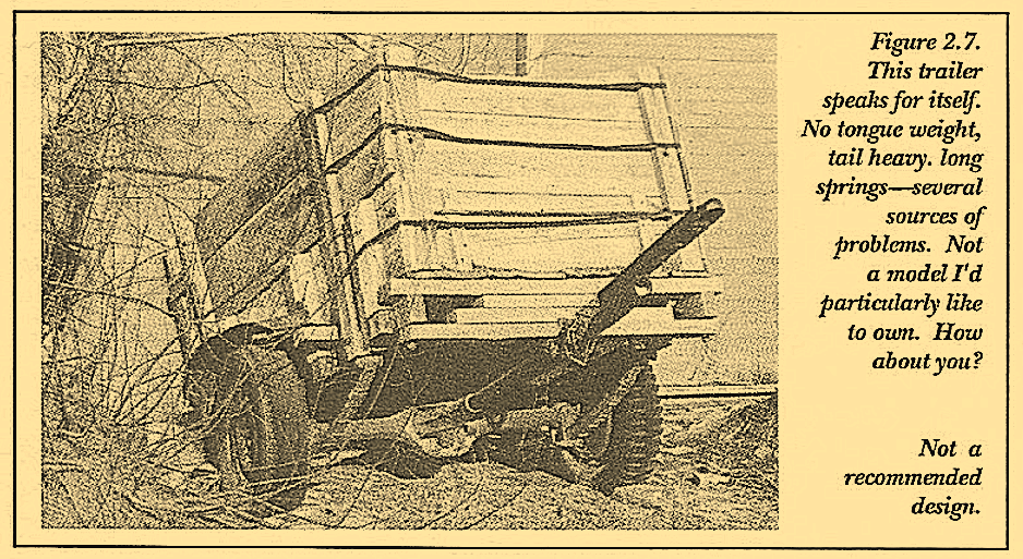
particularly like to own. How about you? Overall Considerations Not a recommended design.
The factors on a trailer that effect the CG location are numerous.
A few are listed here:
- wheel and tire height;
- axle drop and square size;
- spring hanger design and its attachment to the frame;
- spring mounting to axle (above or below);
- type of spring used- slipper, standard, torsion; frame materials used-height and relative position;
- tongue-to-frame and coupler-to-tongue attachment.
These factors can and should be manipulated to make the trailer’s CG acceptable. Generally, the lower the CG, the more apt you are to develop a trailer with towing stability. However, trailers with higher CG’s can be built with towing stability if other factors-tongue length, rear overhang, suspension are adjusted to compensate. Arriving at the right position for the CG in relation to all components and requirements for the trailer is of vital importance. Further guidelines to finding the optimum placement for center of gravity are provided in Volume 3.
