Trailers - Design & Build
A. AXLES
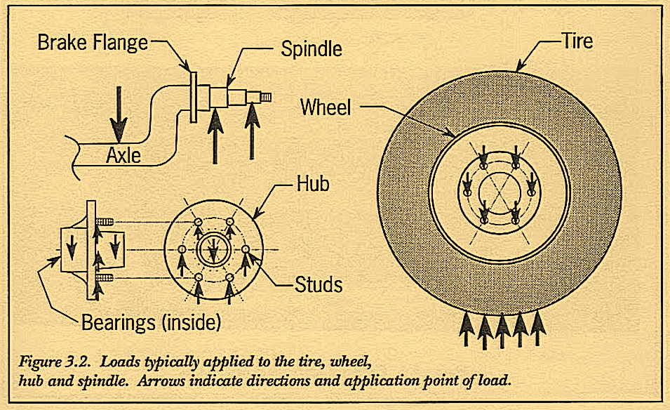
The axle is an important and integral part of the suspension. It is the main horizontal cross-wise bar that carries the vertical downward loads from the frame and cargo. Tension through it also serves to keep the spindles in a horizontal position. The spindles are placed at each end of the axle. Bearings slide onto the spindles and carry the hubs. Onto the hubs are bolted the wheels (or rims) with mounted tires. The tires rest on the ground, supporting the entire load from the trailer weight and cargo. Figure 3.2 illustrates terminology and the direction of forces on each suspension part as the loads transfer from one component to the next. Each part is an important element as it transfers loading through the system.
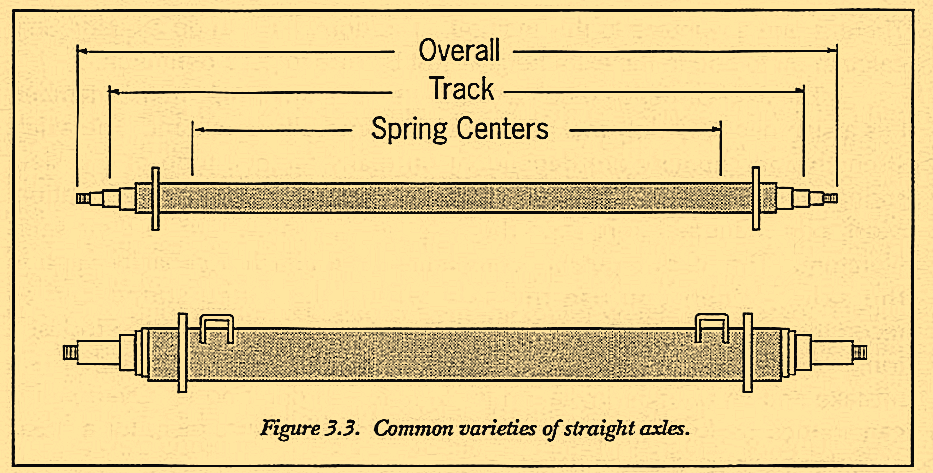
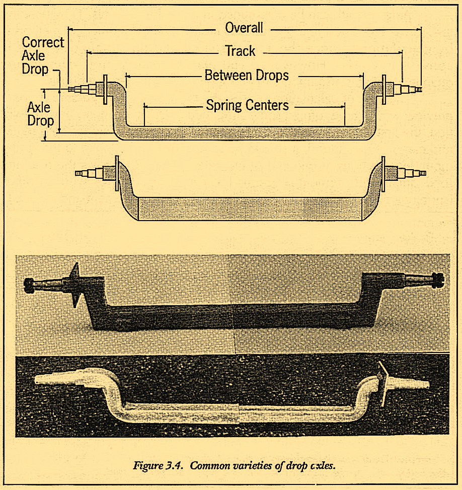
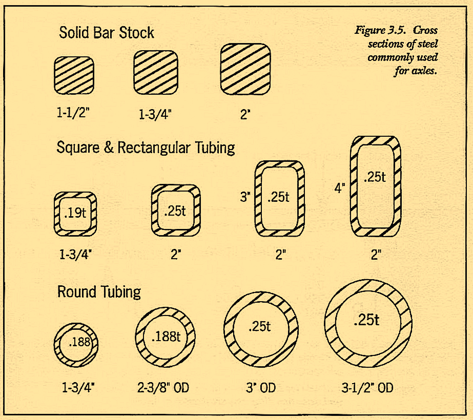
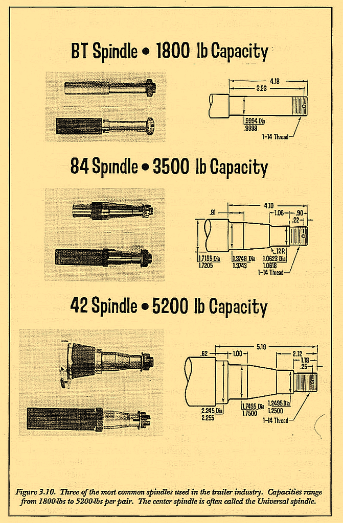
Axles come in all shapes-round, square, rectangular, tubular, solid bar, drop, straight-from dimensions of 1-1/4-in up to 5-in square. The most common cross sections used on axle material are illustrated in Figure 3.5. Axles come in many lengths and capacities, too. Figures 3.3 and 3.4 show some of the more common axle styles available. Popular spindles are shown in Figure 3.10.
Terminology used with straight and drop axles is shown in Figures 3.3 and 3.4. The overall length is taken from the two outer-most extreme points on the axle. This often translates to the overall width of the trailer you are building. And many wheel widths are set up to end close to this plane. The axle track falls between the inner and outer bearings and is used by travel trailer manufacturers that have varying wheel off sets or can accept a different axle. By retaining a standard track, they are sure the tires will fit under the fenders of their coach body. Between-the-drops dimension is useful for defining the outside frame width. By subtracting 1/2-in per side (1-in overall) from this dimension, a maximum frame width providing minimum overhang can be achieved. Spring centers are the points where the spring centering holes are drilled. These are predrilled only with a solid bar axle. If the axle is tubular, drilling weakens the axle far too much. Thus you will receive a small bracket to weld on yourself for aligning these holes. Depending on the axle, the brackets take on several different designs. Two styles of these weld on brackets can be seen in Figure 3.9. The axle drop is used to define the dimension from the hub center to the spring. To know this accurately, it is necessary to query your supplier as to how they determine it. Most manufacturers correctly use a dimension from center of hub to center of axle bar. With this dimension given, one must know the axle OD (outside diameter) to determine the additional height to the top of the spring. If your supplier uses an axle drop from center of hub to bottom of axle, it may mislead you into thinking the two drops are the same, when, in fact, you have less drop with this axle.
There is one advantage to this method. You don’t have to do an additional calculation to add in the extra height. Just be sure to get a definition.
The axle carries as much as, or more than, any single frame member; this assignment and duty makes its strength especially important. The axle’s strength and capacity are dependent on many factors: tube or bar size, spring mounting position, spindle designation, and method of fabrication. Most axle manufacturers state the axle rating somewhere in their sales literature. The more reputable companies even attach a capacity plate to the axle. When you use the axle within the range stated and as recommended you can count on the strength and expect the axle to last a long, long time. Selecting an axle knowing it will be overloaded is a mistake and an outright invitation for trouble-so don’t do it. Overloading can shorten useful life significantly and create the environment for a break at some unexpected future date.
Axle strength can be determined in a number of ways: 1) by bending test, 2) by fatigue test and 3) by calculations. The most practical method is by calculations-since the axle is spared and the amount of work is considerably less. However, if you plan to manufacture axles in any quantity, testing is also important and should be considered seriously.
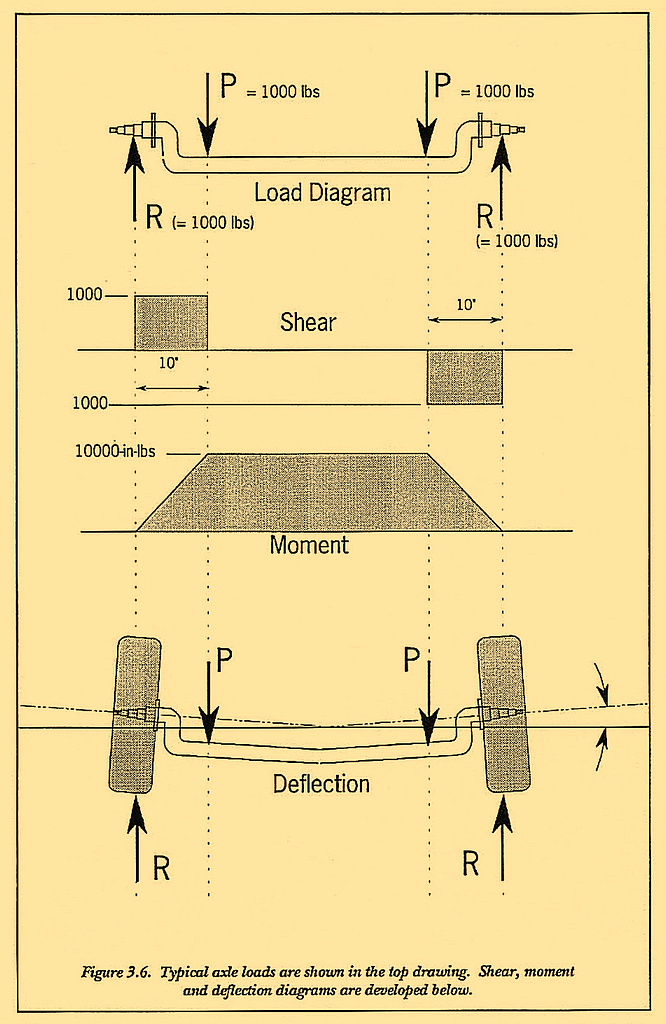
The type of calculations necessary are described in Volume 2. As a preview we have performed some simplified calculations here. As you will find, the first step is to calculate the applied load-this includes both trailer and cargo. Once found, it should be split in half and applied to the spring mounting positions at one end of the axle. Figure 3.6 shows the resulting load, shear and moment diagrams for a load of 2000-lbs with an offset (spring perch to tire) of 10 inches. Once the bending moment and material of choice (steel, aluminum) is known, the required moment of inertia for the load can be calculated.
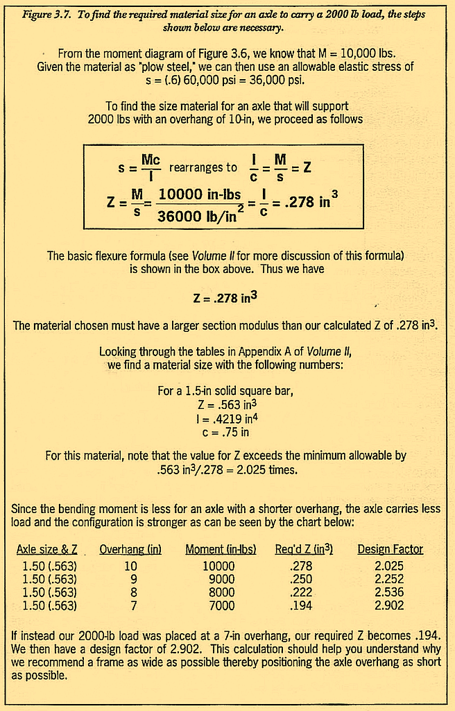
Knowing this, an appropriate material cross section can be selected. Figure 3.7 shows the calculations to select such an axle for this 2000-lb load. Although choices of material other than solid bar are available, we have used only 1-1/2-in solid bar as an example.
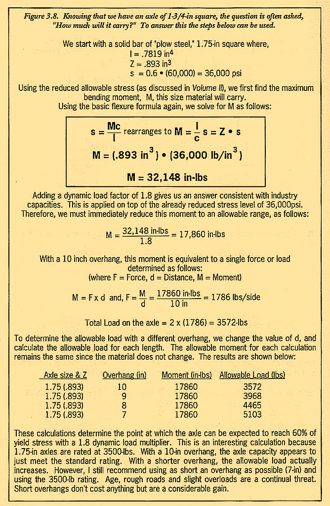
If you already know the axle size and want to determine its strength or carrying ability, a slightly different approach to the problem is required. Figure 3.8 determines the carrying ability of a 1-3/4-in axle with a 10-inch overhang and then compares a 9-in overhang with an 8-in overhang. “Plow steel,” which has a tensile stress of 110,000 psi and a yield point of 60,000 psi, is assumed as the material. As explained in Volume 2, the yield stress is reduced to an allowable of (.6) x 60,000 = 36,000 psi. Stresses below this allowable point are regarded as being within the elastic range. (NOTE: It is not proper to use the ultimate strength-we want to know when it will bend, not break.) The final allowable load with an overhang of 10-inches is then 1786-lbs/side, or 3572-lbs total. With an overhang of 8-in, the allowable load increases to 1984-lbs/side or 3968-lbs total-an 11% increase in strength! The moral of this story is to shorten your axle overhang by positioning the frame side rails out as far as possible.
Strength can be estimated with calculations-by far the easiest method of arriving at a decision and getting you into the ballpark. Calculations, however, do not replace the testing process, they only preceed it. With welded connections and complicated load paths (commonly found on tubing axles), testing is especially important.
A bending test will give the static strength of the axle. Merely place the axle in an H-Frame press and note the force at which permanent deformation occurs; i.e., the metal bends and does not return to its original position. To obtain an accurate reading, the set-up should be configured so that the push points are at the hub center and the spring mounting holes (Figure 3.3), just as it would be on a trailer. Loading it otherwise gives erroneous results. All in all this is an easy test. Unfortunately, it will destroy the axle you’re testing. In addition, the data obtained is useful only if your trailer will sit still during its loaded life.
A fatigue test is more difficult but will more accurately reflect an axle’s use and ultimate capacity. This test also has a good chance of destroying the axle. A load that will fatigue an axle to breaking is usually much smaller than the static load to bend it. Stress concentrations which result from holes, bends, welds or changes in shape reduce load carrying ability. The exact amount of load reduction is difficult to predict and may even vary from axle to axle. Hence, the axle you choose for this test should be relatively free of those things-but it should be representative of the axle group you are checking out.
The effect of stress concentrations from shape and the axle’s expected load carrying ability can be determined by testing several axles in this way. A test fixture similar to the one used in the bend test is necessary. Designing such a test fixture can be quite a project in itself and is often wisely left to an independent testing lab as is the actual testing. Instead of the static load from the H-Frame press, the load must be set up so it can be applied and released, applied and released, applied and released for at least 1 million cycles. . . or until the axle breaks at some smaller number of cycles. After destroying a few samples in this fashion, the load at which that style of axle will last forever is eventually defined. Because this procedure more closely imitates the axle’s environment, a much more accurate figure of an axle’s strength is attainable.
Beyond the calculation and testing process, there are certain configurations of an axle that will basically improve strength and resistance to fatigue; and others that won’t. Stress concentrations worsen resistance, while a smooth, straight, uninterrupted section improves it. Figure 3.9 illustrates configurations which worsen fatigue resistance:
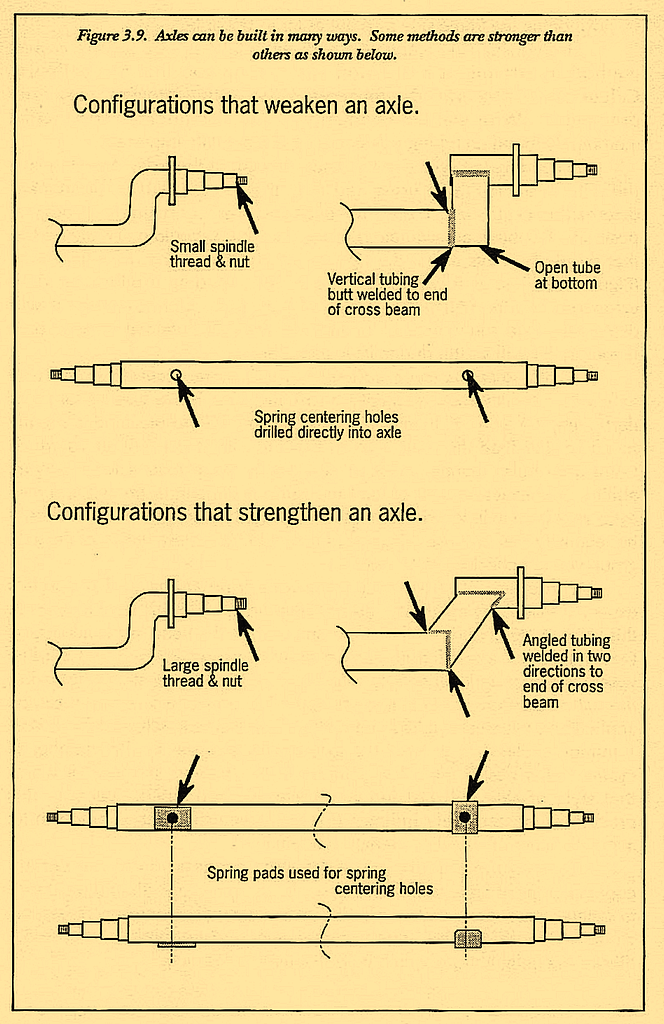
Figure 3.9 illustrates configurations which worsen fatigue resistance:
- End nut threads are much smaller than the outer bearing diameter-usually requiring a 3/4-inch nut rather than a 1-inch nut;
- Welded connections are used to weld a spindle to a tube to make an axle without consideration for the load paths;
- Spring centering holes are drilled directly into the material;
Strength, reliability and fatigue resistance of an axle will improve if:
- An end nut close to the same diameter as the outer bearing-usually a 1-inch diameter;
- A solid bar bent axle is chosen rather than one of poorly designed welded construction;
- A spring centering hole is welded onto the axle with a plate (called a spring pad) rather than drilled into the axle; 4) Welded axles are heat treated to normalize the uncon- trolled hardening and built-in stresses from weld heat.
If this discussion sounds like welded axles are to be avoided, you may be right. Welded axles certainly have more areas where failure can begin and should at least be checked out carefully. On the other hand, welded axles do afford one advantage. They do not require special equipment or tooling, and are therefore very cheap to manufacture and can be built by just about anybody. Solid bar axles, which have been used for many years, do not have the features which invite the stress concentrations of welded axles. As discussed in Volume 2, welding’s inherent risk of lack of penetration, undercuts which create invisible stress concentrations and the change of material properties right next to the weld, can be lethal in a component as important as an axle. Consumers should be especially wary of welded axles and should be warned to carefully scrutinize the axle on the trailer they are considering purchasing.
Don’t get me wrong, most manufacturers whose primary business involves axles and whose designs and procedures are obviously well thought out are not part of this category. Welded axles if carefully designed and tested can be effective and endure as required and expected. Capacities need to be checked carefully and construction supervised with an eagle-eye. To gain the advantage of flexibility and the low cost of a welded axle while maintaining a decent amount of structural integrity, forged drop spindles have recently found their way to market. These axles although welded, are fabricated under very controlled conditions and appear to be rated conservatively. This axle style is shown in Figure 3.4.
Considering their importance and the gravity of the single duty assigned to them, axles must be attributed a high priority when it comes to defining adequate strength.
